
MMC5 audio
Nintendo’s MMC5 mapper provides extra sound output, consisting of two pulse wave channels and a PCM channel. The pulse wave channels behave almost identically to the native pulse channels in the NES APU.
The sound output of the square channels are equivalent in volume to the corresponding APU channels, but the polarity of all MMC5 channels is reversed compared to the APU.
The PCM channel is similarly equivalent in volume to the APU with equivalent input, and inverted, but using the extra high bit of input it can become twice as loud.
- Write only
- Reset detection not used
These registers manipulate the MMC5’s first pulse wave channel, which functions the same as to those found in the NES APU except for the following differences:
- $5001 is not implemented. The MMC5 pulse channels will not sweep, as they have no sweep unit.
- Frequency values less than 8 do not silence the MMC5 pulse channels; they can output ultrasonic frequencies.
- Length counter operates twice as fast as the APU length counter (might be clocked at the envelope rate).
- MMC5 does not have an equivalent frame sequencer (APU $4017); envelope and length counter are fixed to a 240Hz update rate. Based on die images, the exact rate appears to be the M2 frequency divided by the simplified integer 7424, which gives 241.079Hz. However, a bench test has not been performed to confirm this 0.45% difference.
MMC5’s NTSC-only length counter lookup table doesn’t implement the lowest output bit, which is always 0. Accounting for this, it appears to have 1 difference versus the APU’s NTSC lookup table:
| 5-Bit Register Value | APU 7-Bit Count Value | MMC5 7-Bit Count Value |
|---|---|---|
| $00 | $0A | $0A |
| $01 | $FE | $FE |
| $02 | $14 | $14 |
| $03 | $02 | $02 |
| $04 | $28 | $28 |
| $05 | $04 | $04 |
| $06 | $50 | $50 |
| $07 | $06 | $06 |
| $08 | $A0 | $A0 |
| $09 | $08 | $08 |
| $0A | $3C | $3C |
| $0B | $0A | $0A |
| $0C | $0E | $0E |
| $0D | $0C | $0C |
| $0E | $1A | $1A |
| $0F | $0E | $0E |
| $10 | $0C | $0C |
| $11 | $10 | $10 |
| $12 | $18 | $18 |
| $13 | $12 | $12 |
| $14 | $30 | $30 |
| $15 | $14 | $14 |
| $16 | $60 | $60 |
| $17 | $16 | $16 |
| $18 | $C0 | $C0 |
| $19 | $18 | $18 |
| $1A | $48 | $48 |
| $1B | $1A | $1A |
| $1C | $00 | $10 |
| $1D | $1C | $1C |
| $1E | $20 | $20 |
| $1F | $1E | $1E |
Other features such as the envelope and phase reset are the same as their APU counterparts.
These registers manipulate the MMC5’s second pulse channel.
- Read/Write
- Reset detection is used
7  bit  0
---- ----
0xxx xxx0  Reset Value
---- ----
Ixxx xxxM
|       |
|       +- Mode select (0 = write mode. 1 = read mode.)
+--------- PCM IRQ enable (1 = enabled.)
7  bit  0
---- ----
Ixxx xxxM  MMC5A default power-on read value = $01
|       |
|       +- Revision (0 = Letterless MMC5. 1 = MMC5A.)
+--------- IRQ (0 = No IRQ triggered. 1 = IRQ was triggered.)
Reading $5010 acknowledges the IRQ and clears this flag.
- Write only
- Ignores direct writes in PCM read-mode
- Write-by-read writes to this register in PCM read-mode.
- Reset detection not used
- Power-on state effectively random
7  bit  0
---- ----
WWWW WWWW
|||| ||||
++++-++++- 8-bit PCM data
This functions similarly to the NES APU’s register $4011, except that all 8 bits are used.
Shin 4 Nin Uchi Mahjong is the only game to use the extra PCM channel ($5011).
Writing $00 to this register will have no effect on the output sound, and does not change the PCM counter.
Pin 2 no-load voltage very closely follows the equation:
Voltage = [(DAC value / 255) * (0.4 * AVcc)] + (0.1 * AVcc)
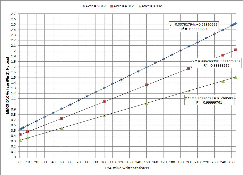
The DAC output is very low impedance – it holds its voltage true under load. To protect itself, the output also has a current limit. The current limit level depends on AVcc. MMC5A measured current limit in microAmps = (42.178 * Avcc) - 36.808. It is unknown, but quite doubtful, that prolonged exposure to current limit mode could cause damage to the DAC or other parts of the MMC5. Since current limit mode would cause audible distortion, it should be considered a self-protection feature that should be avoided. In practice, with Avcc = 5V, the DAC output pin should drive 15kohms or higher to avoid current limit mode.
The same MMC5A chip, tested with repeated power cycles on different days of the week and different moon phases, etc, has been observed to power on with a DAC voltage equivalent to DAC value $EF or $FF. No other power-on values have been observed. This voltage is not affected by a reset detected when M2 stops toggling.
The MMC5’s DAC is changed either by writing a value to $5011 (in write mode) or reading a value from $8000-BFFF (in read mode). If you try to assign a value of $00, the DAC is not changed; an IRQ is generated instead and must be acknowledged by reading $5010.
This functionality can be used in an unrolled loop to stream 8-bit PCM from ROM and terminate at $00:
; write mode
WriteModePCM:
  lda PCMData ; +4 cycles
  sta $5011 ; +4 cycles = 8 cycles per DAC update
  lda PCMData+1
  sta $5011
  ; ... until a $00 write fires an IRQ

; read mode
; appears to be intended for making the unrolled loop tighter (thus improving playback rate)
ReadModePCM:
  lda PCMData ; 4 cycles per DAC update
  lda PCMData+1
  ; ... until a $00 read fires an IRQ

; must be within $8000-$BFFF for read mode
; should be in a switchable bank for code reuse
PCMData:
 .byte $AA, $55
 ; ...
 .byte $00
(pseudocode)
(On DAC write)
    if(value=0)
        irqTrip=1
    else
        irqTrip=0

(On $5010 write)
    irqEnable=value.bit7

(On $5010 read)
    value.bit7=(irqTrip AND irqEnable)
    irqTrip=0

Cart IRQ line=(irqTrip AND irqEnable)
- Read/Write
- Reset detection not used
This register is analogous to the APU Status register found within the NES at $4015, except that only the bottom 2 bits are used; being for the MMC5’s two pulse channels.
Expansion audio hardware configuration from HVC-ETROM-02:
            R3 15k   C4 100n
From 2A03 ---/\/\/-----||------+           R4 10k
(Cart.45)                      |   +--------/\/\/---------+
                               |   |           _          |
            R2 15k   C3 100n   |   | (MMC5.1) | \         +--- To RF
MMC5 DAC ----/\/\/-----||------+---+----------|-  \       |    (Cart.46)
(MMC5.2)                       |              |    >------+
                               |   intvref ---|+  / (MMC5.100)
            R1 15k   C2 100n   |              |_/
MMC5 Pulse --/\/\/-----||------+
(MMC5.3)
- Famicom expansion hardware recordings - forum thread with MMC5 test ROMs and recordings confirming various MMC5 audio features.
- MMC5 volume test - hotswap test ROM for investigating MMC5 volume.